Bikemonkey's NC30
-
Icemaestro
- Familiar Member
- Posts: 331
- Joined: Wed Nov 27, 2013 6:45 am
Re: Bikemonkey's NC30
What are these ccfl rings? :-) (just out of interest)
-
jim157

- Admin NWAA

- Posts: 1004
- Joined: Mon May 17, 2010 7:15 pm
- Bike owned: A few small ones
- Location: Norwich

-
bikemonkey
- NWAA Supporter

- Posts: 1525
- Joined: Tue Dec 27, 2011 12:33 pm
- Bike owned: 92 NC30, 90 VFR750
- Location: Oxfordshire
Re: Bikemonkey's NC30
Drunkn Munky wrote:I bet you loved opening that box from webike, badges arrived today cheers pal.
Yeah I did
Not a problem mate.
Cheers for that Jim, I didn't know what it stood for either
I do however know that once you've taken the plastic casing off them then there's nothing that the headlight bulb can melt
-
micpec

- Site Supporter

- Posts: 1298
- Joined: Sat May 03, 2008 9:11 pm
- Bike owned: NC35’s, NC30 sold, MC34 many
- Location: The Netherlands
Re: Bikemonkey's NC30
Nice stuff from webike!
Have two AC ryan tornado2 pc fans including ccfl 80mm still brand new here in original box (unopened) if you are still looking for them (bought them once for the custom pc, but never used them because I bought a laptop).
Have two AC ryan tornado2 pc fans including ccfl 80mm still brand new here in original box (unopened) if you are still looking for them (bought them once for the custom pc, but never used them because I bought a laptop).
"Action without Philosophy is a lethal weapon; Philosophy without action is worthless"
-
bikemonkey
- NWAA Supporter
- Posts: 1525
- Joined: Tue Dec 27, 2011 12:33 pm
- Bike owned: 92 NC30, 90 VFR750
- Location: Oxfordshire
Re: Bikemonkey's NC30
Cheers micpec, I used 85mm rings in the headlights and they were literally just big enough.
90mm or 95mm would be a much better option but the company I got them from couldn't get any in that size.
90mm or 95mm would be a much better option but the company I got them from couldn't get any in that size.
-
micpec
- Site Supporter
- Posts: 1298
- Joined: Sat May 03, 2008 9:11 pm
- Bike owned: NC35’s, NC30 sold, MC34 many
- Location: The Netherlands
Re: Bikemonkey's NC30
90 or 95mm are not that widely used as CCFL's I remember. In the past decade the 80mm or near sizes were available due to the PC market and custom build desktop towers by hobbyist etc. I was triggered by some members back at that time on the oldforum, they put the headlight units in the hot oven and pealed the sealing off, then lift the glass from the housing and put the CCFL's in and fully kitted these back.
In general CCFL technology is getting out of the league in coming 1.5~2 years for professional purposes first. At my contractor we phased-out the CCFL monitor panels and switch over to new high level standard (these high standards are required due to government and healthcare regulations worldwide) LED en pretty soon by OLED technology.
In general CCFL technology is getting out of the league in coming 1.5~2 years for professional purposes first. At my contractor we phased-out the CCFL monitor panels and switch over to new high level standard (these high standards are required due to government and healthcare regulations worldwide) LED en pretty soon by OLED technology.
"Action without Philosophy is a lethal weapon; Philosophy without action is worthless"
-
bikemonkey
- NWAA Supporter
- Posts: 1525
- Joined: Tue Dec 27, 2011 12:33 pm
- Bike owned: 92 NC30, 90 VFR750
- Location: Oxfordshire
Re: Bikemonkey's NC30
So I've had more time than I thought, and the Koso Dash was easier to install than the instructions made it sound.
Here's me being impatient and opening it while at work.

And the size difference between original and RX2.

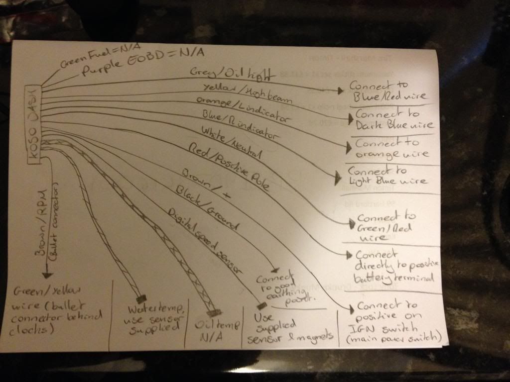
Started figuring out the dash on Thursday night and drew out my own "wiring diagram" to help myself.
Seemed easy enough once I'd got my head round it. So I got hold of the sub-loom from the original clocks (I've got a spare on the way to replace it if I need to go back to original) and started wiring that in as it was easier than butchering the main loom. I kept forgetting to put the shrink wrap on before soldering, so ended up just taping a couple of joints
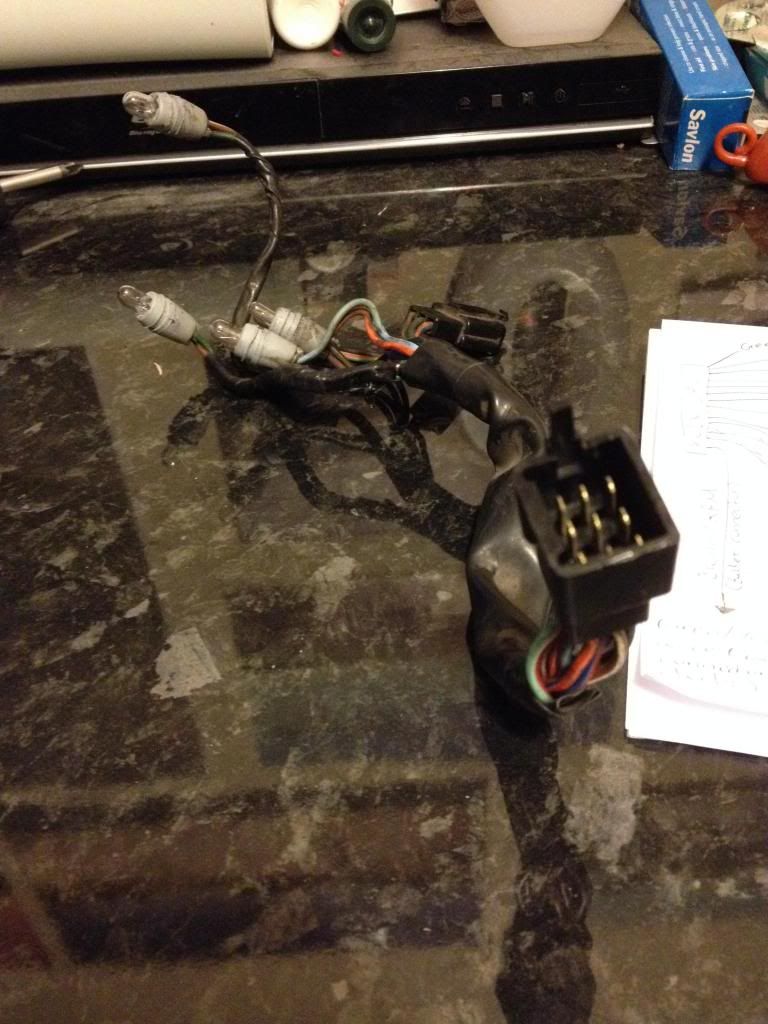
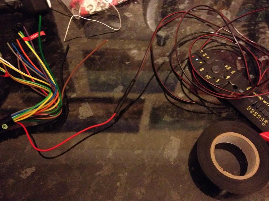


The un-used wires from both ends were taped up to neaten things. At this point I left everything else loose to allow for any routing issues, as I didn't fancy wrapping and un-wrapping something because I'd got it wrong.

Yesterday morning I managed to finish the soldering on the clock loom before work and started to figure out where everything would go.
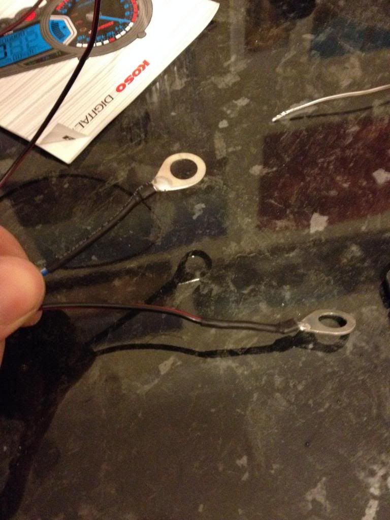
Then this morning I got the clock mounted before work and looked at how to mount the speed sensor. Because I have caliper brackets for my 929/SP1 calipers, there wasn't anywhere I could mount the bracket supplied where it would work. So I made up a small right angle bracket at work and used it to mount the sensor using the fork pinch bolt.


This afternoon I cracked on and connected up the positive and earth for the clocks, then begrudgingly used one of the parallel connectors provided in the pack to connect up the ignition switch. Didn't take a photo as I don't want to shame the thread with those horrid red things.


Temp sensor. It was easy as the sensor provided is exactly the same thread as the original, and the coolant didn't piss out because the airlock kept it in. No need to drain the rads
I may actually change the temp sensor to appear on the oil temp part of the dash as I have to choose between the time and temp atm, bit annoying.


Then my speed sensor solution.

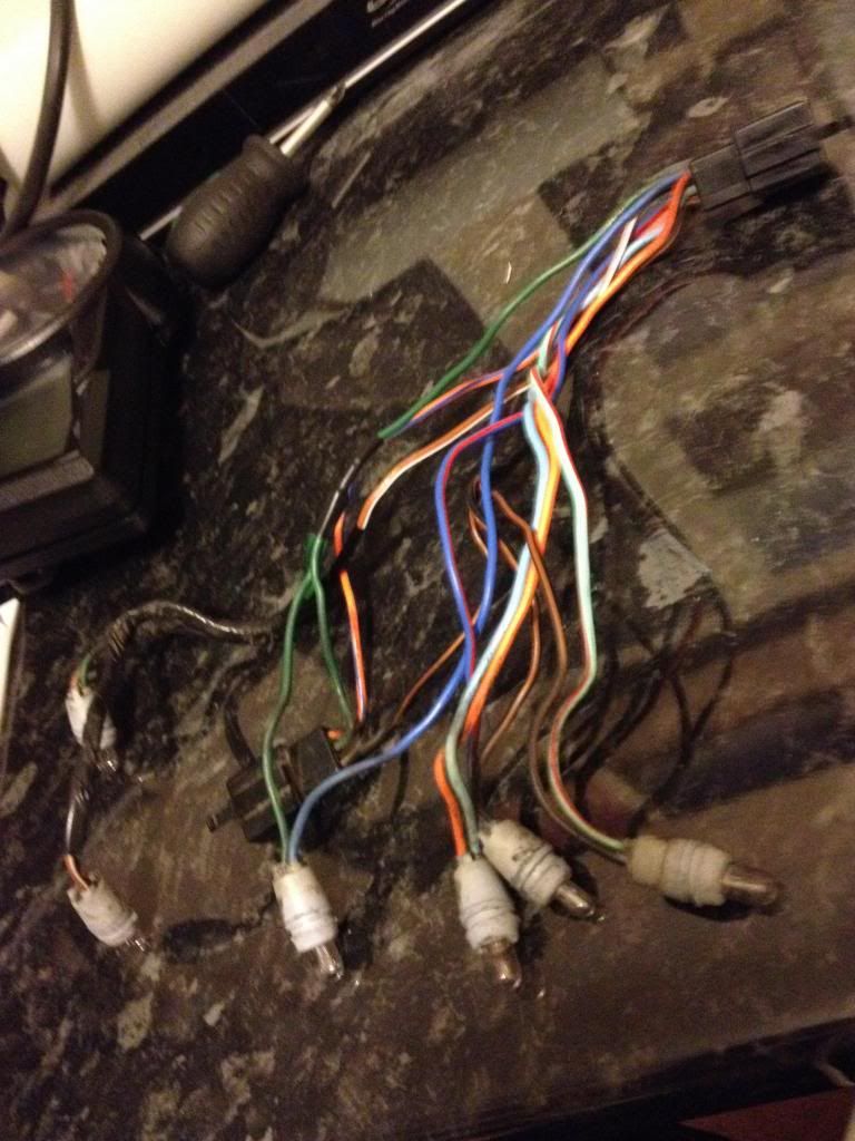
Lovely mess of wires to tidy up. I could actually do with building a new loom, there's so many new wires running everywhere from the dash, low beam relay, voltmeter, alarm, manual fan switch and charging system upgrade.....


Then was to flick the ignition on to see if it was working, and it was, perfect.
Apart from the tacho, that wasn't working at all. I had thought that I could just plug the tacho into the original rpm wire coming from the CDI and it'd work. Nope, wasn't having it.
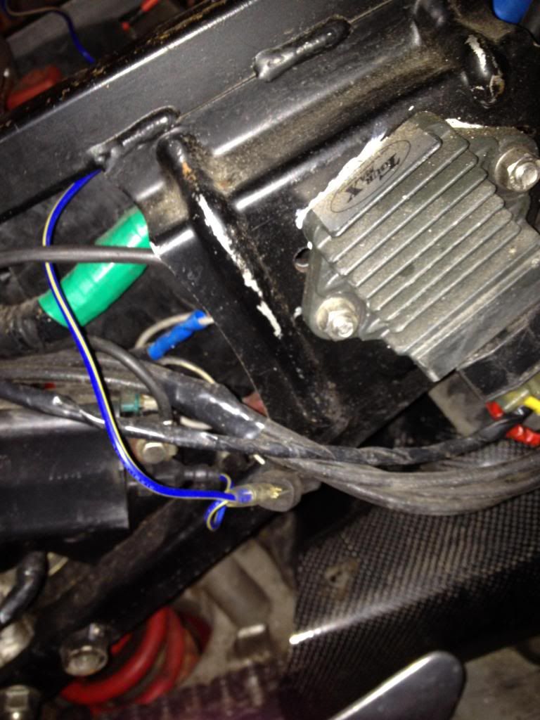
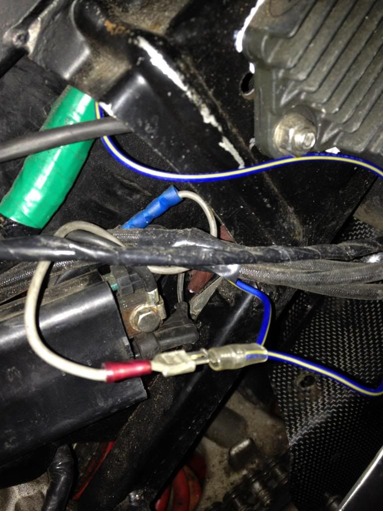
Solution was to use one of the supplied wires to put in a parallel feed from the rear coil pack. I at first managed to connect it to the negative on the coil and it wouldn't work. 10 minutes of head scratching later and I swapped it onto the positive and it worked.
The correct setting for the tacho was four stroke 2 piston. Probably because of the wasted spark ignition, but that's what worked.


I had clearance issues with the top fairing at first, which was a bit annoying as I thought the dash was set perfectly for me to see it. I tilted it forward 1 position and it just fits. I can still see it pretty well, and it'll work better for chin on the tank riding (not that I do much of that anyway).
The tacho still isn't working perfectly however, the signal being analogue means that the digital tacho is very jumpy and doesn't read perfect. I've been reading online from google searches and the solution seems to be a resistor put inline with the signal wire, but no-one seems to specify what resistance? Maybe it's different for different bikes? Anybody know?
Anyway here's a short video of it working.
http://s1126.photobucket.com/user/olive ... 3.mp4.html
Will just have to wait til tomorrow/when it's not raining to test the speedo properly, as I got the tire circumference from a bridgestone size table. Should work, if not I'll just have to measure it by hand.
I still haven't got that exhaust badge fitted yet though, maybe tomorrow.
Here's me being impatient and opening it while at work.
And the size difference between original and RX2.
Started figuring out the dash on Thursday night and drew out my own "wiring diagram" to help myself.
Seemed easy enough once I'd got my head round it. So I got hold of the sub-loom from the original clocks (I've got a spare on the way to replace it if I need to go back to original) and started wiring that in as it was easier than butchering the main loom. I kept forgetting to put the shrink wrap on before soldering, so ended up just taping a couple of joints
The un-used wires from both ends were taped up to neaten things. At this point I left everything else loose to allow for any routing issues, as I didn't fancy wrapping and un-wrapping something because I'd got it wrong.
Yesterday morning I managed to finish the soldering on the clock loom before work and started to figure out where everything would go.
Then this morning I got the clock mounted before work and looked at how to mount the speed sensor. Because I have caliper brackets for my 929/SP1 calipers, there wasn't anywhere I could mount the bracket supplied where it would work. So I made up a small right angle bracket at work and used it to mount the sensor using the fork pinch bolt.
This afternoon I cracked on and connected up the positive and earth for the clocks, then begrudgingly used one of the parallel connectors provided in the pack to connect up the ignition switch. Didn't take a photo as I don't want to shame the thread with those horrid red things.
Temp sensor. It was easy as the sensor provided is exactly the same thread as the original, and the coolant didn't piss out because the airlock kept it in. No need to drain the rads
I may actually change the temp sensor to appear on the oil temp part of the dash as I have to choose between the time and temp atm, bit annoying.
Then my speed sensor solution.
Lovely mess of wires to tidy up. I could actually do with building a new loom, there's so many new wires running everywhere from the dash, low beam relay, voltmeter, alarm, manual fan switch and charging system upgrade.....
Then was to flick the ignition on to see if it was working, and it was, perfect.
Apart from the tacho, that wasn't working at all. I had thought that I could just plug the tacho into the original rpm wire coming from the CDI and it'd work. Nope, wasn't having it.
Solution was to use one of the supplied wires to put in a parallel feed from the rear coil pack. I at first managed to connect it to the negative on the coil and it wouldn't work. 10 minutes of head scratching later and I swapped it onto the positive and it worked.
The correct setting for the tacho was four stroke 2 piston. Probably because of the wasted spark ignition, but that's what worked.
I had clearance issues with the top fairing at first, which was a bit annoying as I thought the dash was set perfectly for me to see it. I tilted it forward 1 position and it just fits. I can still see it pretty well, and it'll work better for chin on the tank riding (not that I do much of that anyway).
The tacho still isn't working perfectly however, the signal being analogue means that the digital tacho is very jumpy and doesn't read perfect. I've been reading online from google searches and the solution seems to be a resistor put inline with the signal wire, but no-one seems to specify what resistance? Maybe it's different for different bikes? Anybody know?
Anyway here's a short video of it working.
http://s1126.photobucket.com/user/olive ... 3.mp4.html
Will just have to wait til tomorrow/when it's not raining to test the speedo properly, as I got the tire circumference from a bridgestone size table. Should work, if not I'll just have to measure it by hand.
I still haven't got that exhaust badge fitted yet though, maybe tomorrow.
-
bikemonkey
- NWAA Supporter
- Posts: 1525
- Joined: Tue Dec 27, 2011 12:33 pm
- Bike owned: 92 NC30, 90 VFR750
- Location: Oxfordshire
Re: Bikemonkey's NC30
I may have found a solution to the jumpy tacho.
It seems it's a common problem, and some more electrically minded people have found a solution.
http://www.vfrdiscussion.com/forum/inde ... gen/page-2
It seems it's a common problem, and some more electrically minded people have found a solution.
http://www.vfrdiscussion.com/forum/inde ... gen/page-2
-
bikemonkey
- NWAA Supporter
- Posts: 1525
- Joined: Tue Dec 27, 2011 12:33 pm
- Bike owned: 92 NC30, 90 VFR750
- Location: Oxfordshire
Re: Bikemonkey's NC30
Resistors, diode and some spare wiring ordered this morning ready to sort the tacho out.
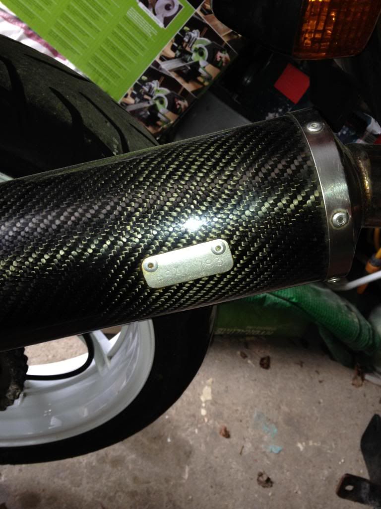
Watched some of the Winter Olympics, got bored and decided to finally re-badge my end can.
I put this little bugger in the way a while ago, so off it came.

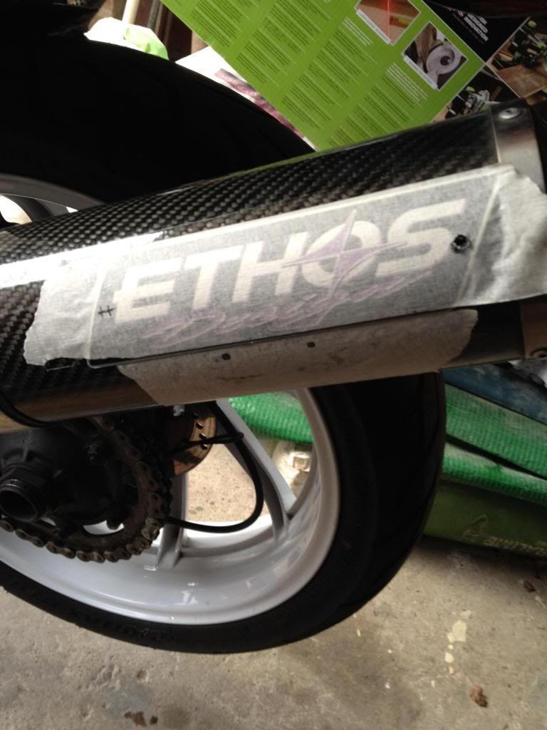
The holes were then covered up by the Ethos badge.

All masked and marked for drilling to rivet.
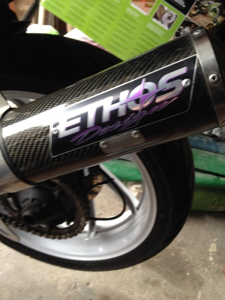
And finally all riveted into place, looks miles better.
Watched some of the Winter Olympics, got bored and decided to finally re-badge my end can.
I put this little bugger in the way a while ago, so off it came.
The holes were then covered up by the Ethos badge.
All masked and marked for drilling to rivet.
And finally all riveted into place, looks miles better.
-
bikemonkey
- NWAA Supporter
- Posts: 1525
- Joined: Tue Dec 27, 2011 12:33 pm
- Bike owned: 92 NC30, 90 VFR750
- Location: Oxfordshire
Re: Bikemonkey's NC30
Haven't been able/arsed to sort out the jumpy tacho yet, but I do have some brackets being made by Kayla that will mount the Koso dash and sensor more to my liking. So I'll probably get that all done in one go.
Besides that I managed to get my mitts on a brand new fitted never used S1000RR shock fitted with an 800lb spring. Cheers Colin (force-v4)
Also got myself an NC30 dogbone from Tomzed, cheers mate, as my NC35 one would have made the shock foul the swinger.
Here's the lovely shiny new stuff.

And here's the crusty old shock quivering in the wake of my spanners! Took quite a bit of dis-assembling to get access.

Offered up the shiny shock after filing down the top mount and an undertray mount on the frame. Used my Dads latest tool, and oscillating thing. Made getting rid of the undertray mount a doddle.

After a fair bit of fiddling, swearing and getting dirty it all went together. Excuse my finger....

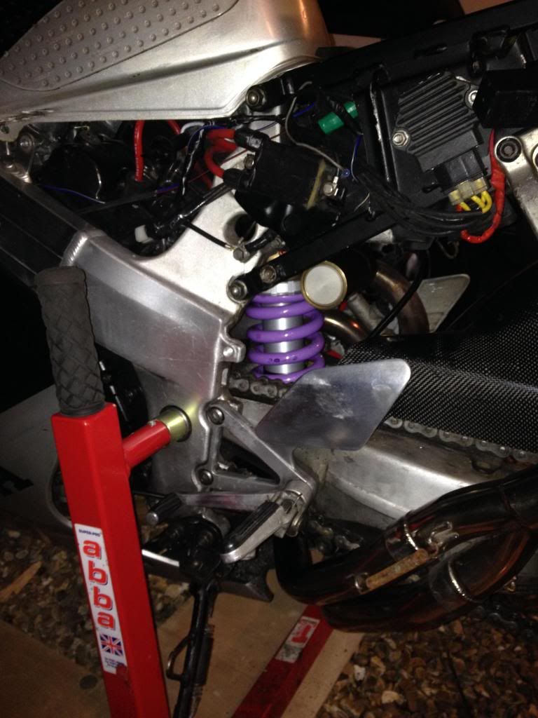
Looks miles better, and just from bouncing the bike in the garage it feels a million miles better. I now have damping! The old knackered shock really was just a pogo stick, this thing feels lovely, and it's not even set-up for that spring.
Hopefully should have the Koso fully sorted next week, then MOT sometime before April as I don't want to have the bike off the road uninsured whilst I'm away (providing I pass my final interview).
Besides that I managed to get my mitts on a brand new fitted never used S1000RR shock fitted with an 800lb spring. Cheers Colin (force-v4)
Also got myself an NC30 dogbone from Tomzed, cheers mate, as my NC35 one would have made the shock foul the swinger.
Here's the lovely shiny new stuff.
And here's the crusty old shock quivering in the wake of my spanners! Took quite a bit of dis-assembling to get access.
Offered up the shiny shock after filing down the top mount and an undertray mount on the frame. Used my Dads latest tool, and oscillating thing. Made getting rid of the undertray mount a doddle.
After a fair bit of fiddling, swearing and getting dirty it all went together. Excuse my finger....
Looks miles better, and just from bouncing the bike in the garage it feels a million miles better. I now have damping! The old knackered shock really was just a pogo stick, this thing feels lovely, and it's not even set-up for that spring.
Hopefully should have the Koso fully sorted next week, then MOT sometime before April as I don't want to have the bike off the road uninsured whilst I'm away (providing I pass my final interview).