Post race-bingle NC30 rebuild - pic thread
Forum rules
Please can you post items for sale or wanted in the correct For Sale section. Items / bikes for sale here will be removed without warning. Reasons for this are in the FAQ. Thanks
Please can you post items for sale or wanted in the correct For Sale section. Items / bikes for sale here will be removed without warning. Reasons for this are in the FAQ. Thanks
-
StrayAlien
- Familiar Member
- Posts: 361
- Joined: Sun Jan 15, 2012 9:27 am
- Bike owned: NC30, Dukes, Hog
- Location: Melbourne, Straya
Re: Post race-bingle NC30 rebuild - pic thread
Wow. That is a great reply. A MotoMoron like me could actually learn a thing or two. :-) Thanks.
However, I think the riveter is stuffed, the mandril (see, I was payaing attention) gets stuck in the riveter after it breaks off. It got a new one for $20 and it does the job fine. The rivets I used for my first attempt were also not quite deep enough ('L/F' in diagram above) - so I went for something a bit meatier. All solid now.
Next is to tin-snip engineer something to hold the ignition relay and the socket point for something to plug the jump start box into (bike is total loss - like its owner!).
-
NGneer

- Site Supporter

- Posts: 794
- Joined: Wed Jan 21, 2009 7:37 am
- Bike owned: x3 NC30,Matchless G80s AJS16ms
- Location: Köln
Re: Post race-bingle NC30 rebuild - pic thread
Glad you got it sorted, and keep up the good work / info.
With the 'old' rivet pliers you have - I suspect that they may work fine, as the 'old' ones I remember being trained up on were designed to still grip the mandril after the rivet had been formed and to release it from the griping bits inside the pliers only when you opened the handles to the max. As I say this was a design feature so you didn't have loads of mandril tails pinging of and getting lost in places you don't want them.
Its the last bit of the opening the handles that finaly release the gripping jaws and then the mandril wil drop out of the front or back (depending on the pliers)...might need a little shake to encourage it
-
Drunkn Munky

- Site Supporter
- Posts: 6313
- Joined: Thu May 01, 2008 9:37 am
- Bike owned: NC30 MC21 TZR FZR GSXR RG MITO
- Location: Kent
Re: Post race-bingle NC30 rebuild - pic thread
Id also say your old piliers are fine, the facom ones i have have done this since new
-
StrayAlien
- Familiar Member
- Posts: 361
- Joined: Sun Jan 15, 2012 9:27 am
- Bike owned: NC30, Dukes, Hog
- Location: Melbourne, Straya
Re: Post race-bingle NC30 rebuild - pic thread
I love this community! Say you've got some crap river pliers and you get help and opinions! Nice one. :-)
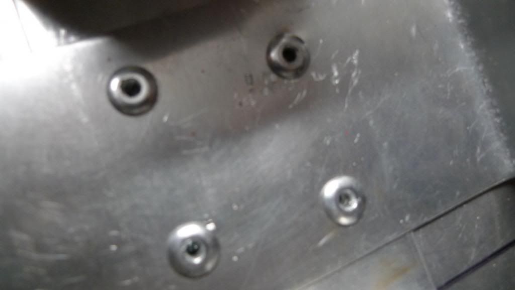
I found out with the rivet pliers (see, I *am* learning) that you do need to open them to their widest to get the broken madril out, but ... ain't happening with 'deceased estate' pliers, but good with the new cheapie one. Besides I went out and got some more sturdy rivets as well. End result is very solid:
Anyways, after all that, in the wee small hours, I finally got the courage to drill and fit the new windscreen to the new top fairing:
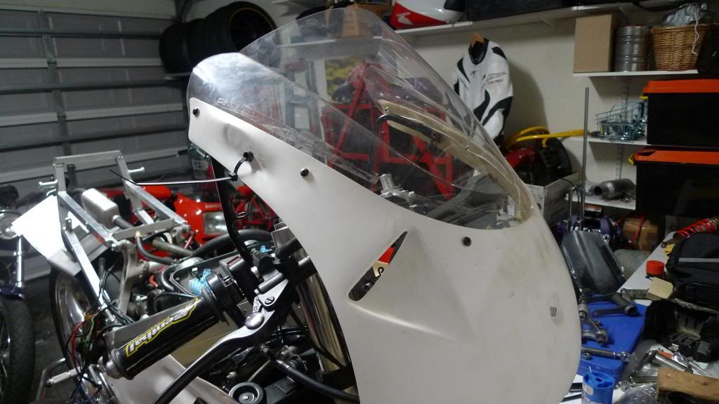
Doesn't seem like much, but I really hate stuffing things up so I've been all cowardly about getting the screen done.
I found out with the rivet pliers (see, I *am* learning) that you do need to open them to their widest to get the broken madril out, but ... ain't happening with 'deceased estate' pliers, but good with the new cheapie one. Besides I went out and got some more sturdy rivets as well. End result is very solid:

Anyways, after all that, in the wee small hours, I finally got the courage to drill and fit the new windscreen to the new top fairing:

Doesn't seem like much, but I really hate stuffing things up so I've been all cowardly about getting the screen done.
-
StrayAlien
- Familiar Member
- Posts: 361
- Joined: Sun Jan 15, 2012 9:27 am
- Bike owned: NC30, Dukes, Hog
- Location: Melbourne, Straya
Re: Post race-bingle NC30 rebuild - pic thread
... and talking of stuffing things up, it is time to get the tin-snip engineering skills back out of the cupboard to finally get the battery box in and other related things sorted. So, given the battery mount will be solid (I hope) let's move onto sorting the relay mount.
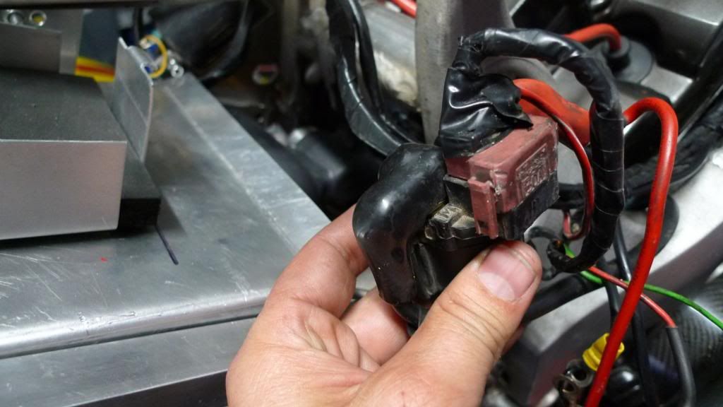
Yes, it is a bit scrappy, but that is how is was when I got it (and still is ...)
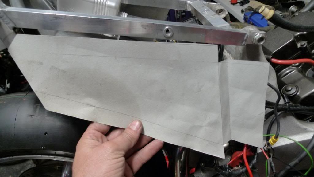
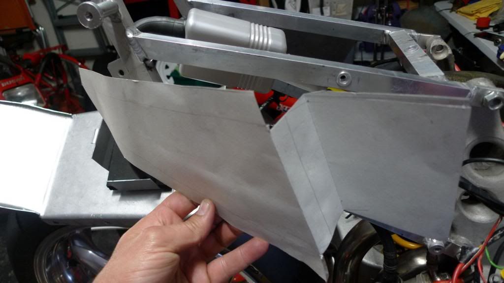
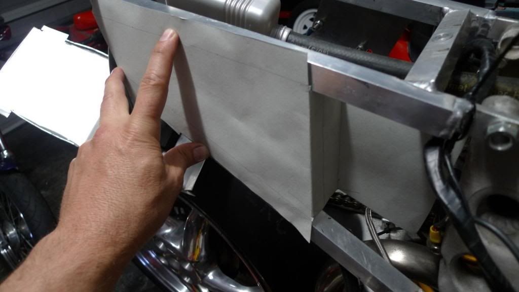
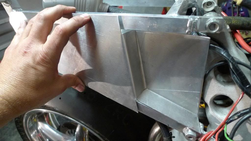
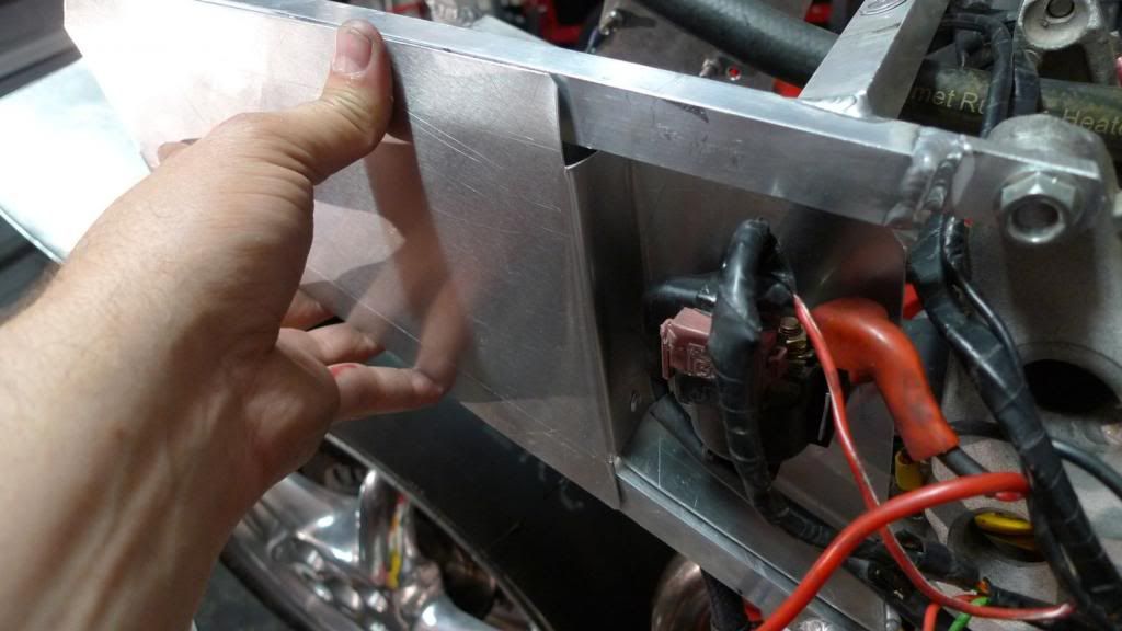
On a stock bike the relay is attached to the side of the battery box - I no longer have an actual battery box, so something else has to be done. The relay can't sit flush with the subframe, it has to go further in to kind-of where the battery box used to be - to make sure the fairing fits. Sort of like this:
So, after a G&T or three I figure I can make something like the subframe right-side plate I already had for the jump-starter plug, but extend it further and make a section that goes 'in'. The paper mock-up shows what I mean:
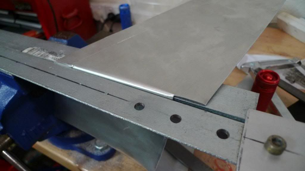
I did some revisions of the paper prototype and when happy enough I set about drawing the same shape on some 1.2mm aluminium sheet. Btw, a tip - I go to a local sheet metal provider and ask for offcuts - it'll cost you about a third of the local hardware store.
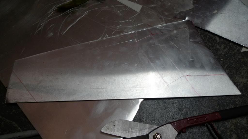
After a screw up and a second attempt I had my shape cut out and could bend it using some scrap 90 degree L-shaped rods. Those paying attention will notice I raped my funcky home-made dial-gauge v-blocks ... :
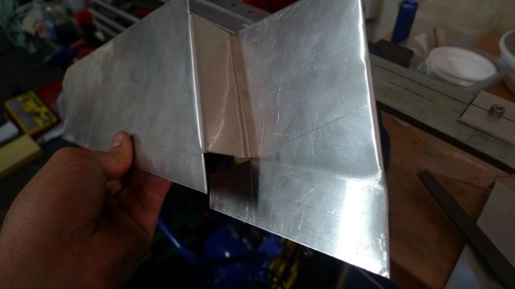
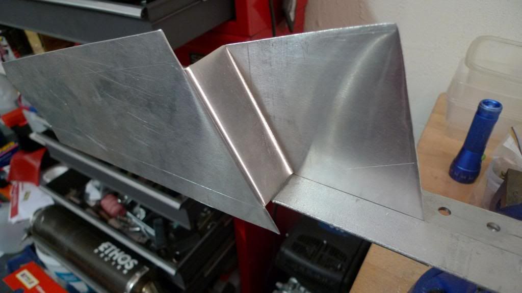
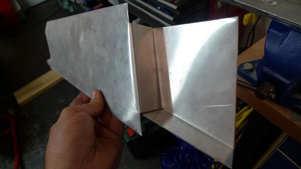
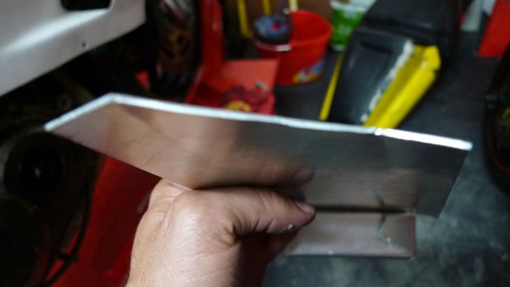
After some bending and maybe another G&T things are starting to take shape:
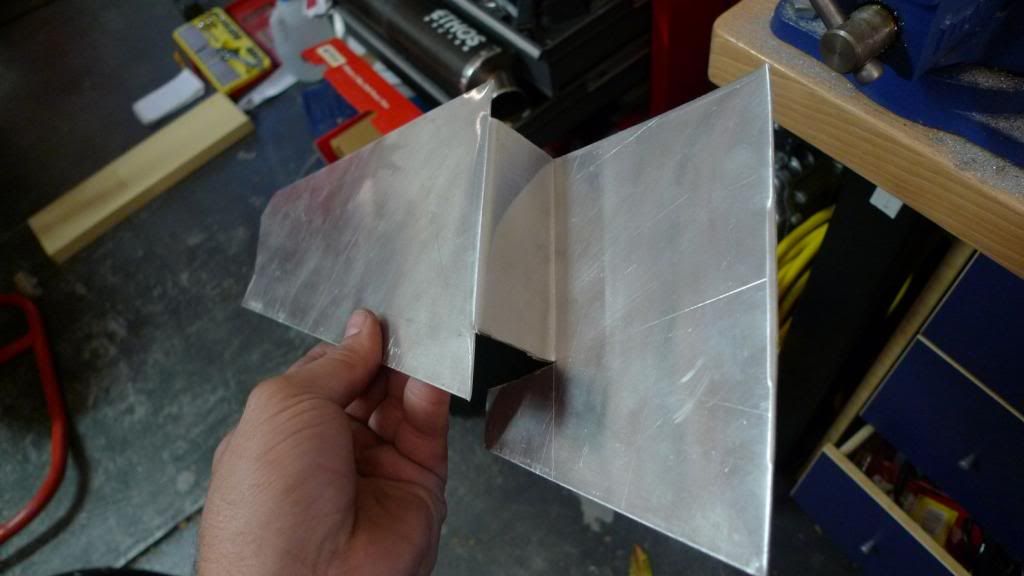
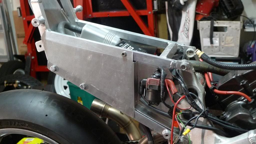
I left a little flap under the 'in' bit to fold up to form a base to seal this area from underneath and to provide a 'box' so I can put some heat shield on the rear and protect it from the heat of the exhausts that are directly below it ..
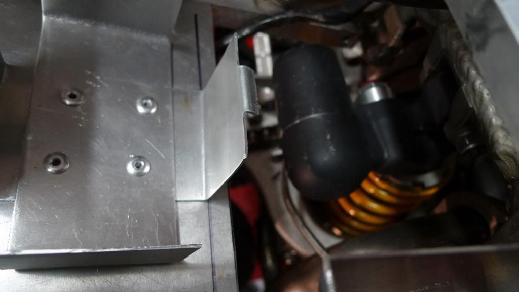
A test fit shows we're doing ok:
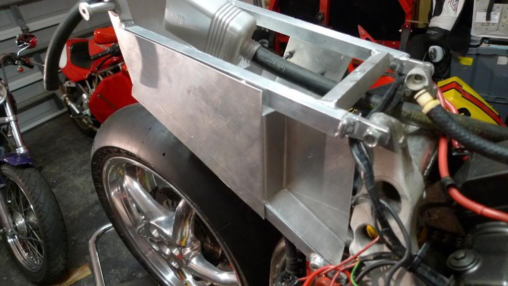
I did need to cut back the plate that the battery sits on to make room for the 'in' bit but I was going to do this anyways. It is good to have room to lift the shock - it makes it much easier to get in and out:
Yes .. you may notice the utterly *shithouse* alignment of the rivets .... that is what you get when doing this in the 'am' hours!
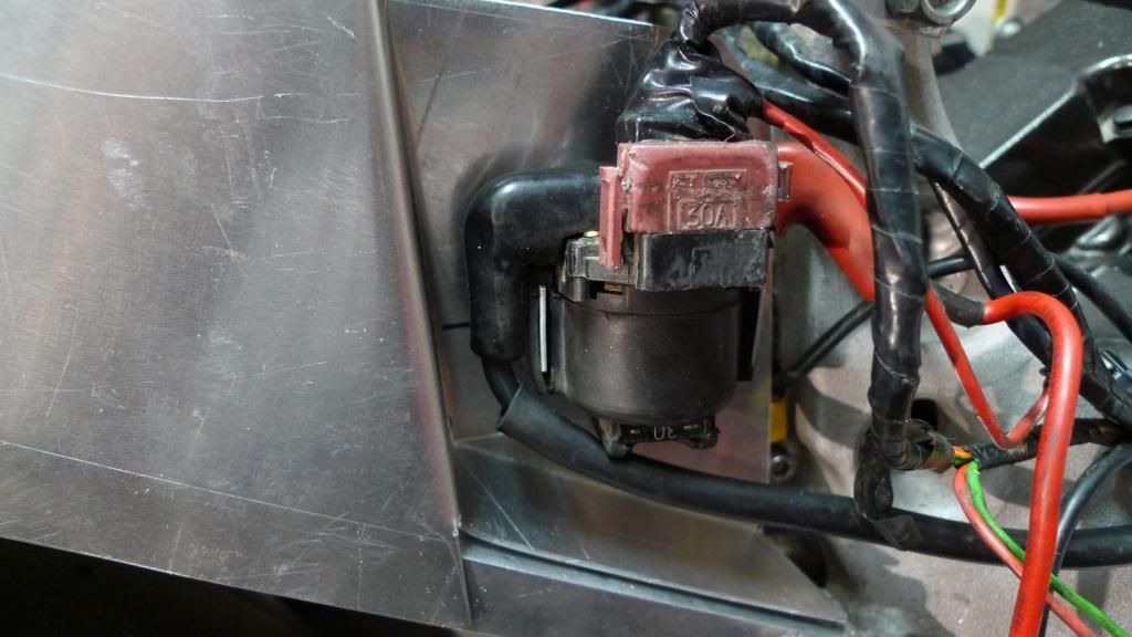
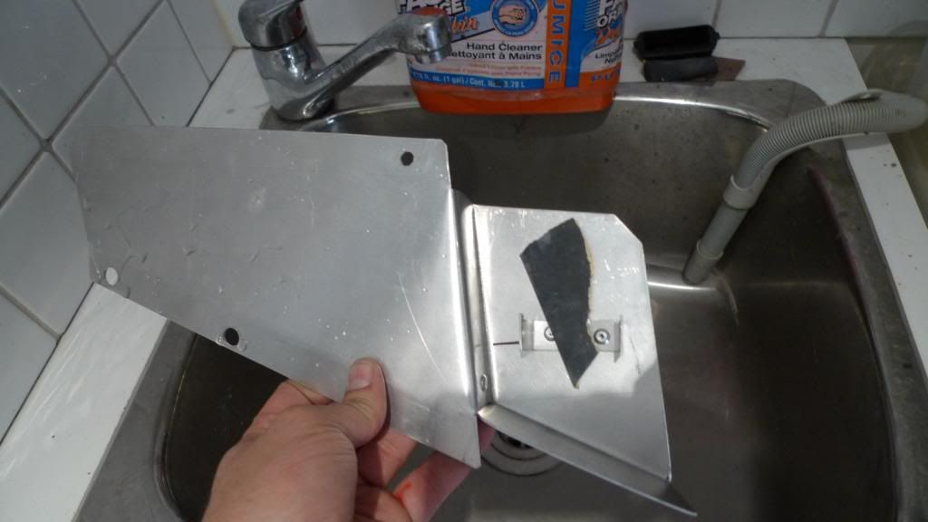
On a stock bike the relay mounts on the side of the battery box on a two little hangers. I need to make something similar to attach to my new construction to do same. Here is my snip-engineered version:
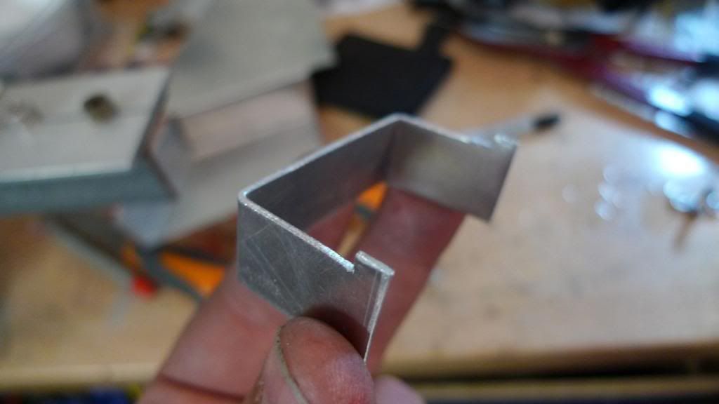
And riveted (yes, the little b*astards still broke off above the rivet head ... so I just filed them off. :-) ):

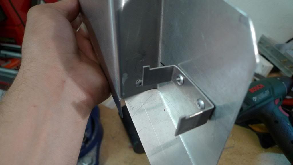
A bend of the edge of the plate to make it fit more snugly along the subframe rails:
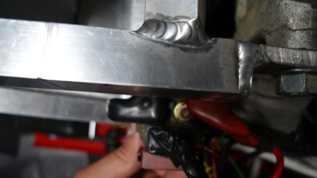
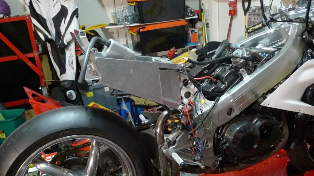
And a test fit:
So, drill the mounting holes and fit it properly to see how it goes:
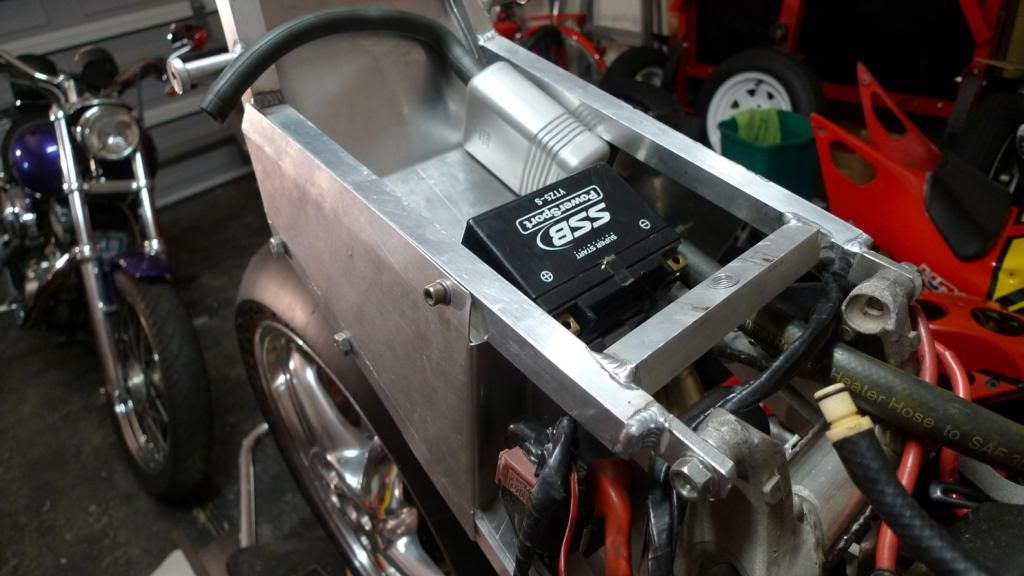
All looking good. Making progress ... excellent.
Time to watch some crap sci-fi action flick.

Yes, it is a bit scrappy, but that is how is was when I got it (and still is ...)
On a stock bike the relay is attached to the side of the battery box - I no longer have an actual battery box, so something else has to be done. The relay can't sit flush with the subframe, it has to go further in to kind-of where the battery box used to be - to make sure the fairing fits. Sort of like this:

So, after a G&T or three I figure I can make something like the subframe right-side plate I already had for the jump-starter plug, but extend it further and make a section that goes 'in'. The paper mock-up shows what I mean:


I did some revisions of the paper prototype and when happy enough I set about drawing the same shape on some 1.2mm aluminium sheet. Btw, a tip - I go to a local sheet metal provider and ask for offcuts - it'll cost you about a third of the local hardware store.

After a screw up and a second attempt I had my shape cut out and could bend it using some scrap 90 degree L-shaped rods. Those paying attention will notice I raped my funcky home-made dial-gauge v-blocks ... :

After some bending and maybe another G&T things are starting to take shape:

I left a little flap under the 'in' bit to fold up to form a base to seal this area from underneath and to provide a 'box' so I can put some heat shield on the rear and protect it from the heat of the exhausts that are directly below it ..


A test fit shows we're doing ok:


I did need to cut back the plate that the battery sits on to make room for the 'in' bit but I was going to do this anyways. It is good to have room to lift the shock - it makes it much easier to get in and out:

Yes .. you may notice the utterly *shithouse* alignment of the rivets .... that is what you get when doing this in the 'am' hours!
On a stock bike the relay mounts on the side of the battery box on a two little hangers. I need to make something similar to attach to my new construction to do same. Here is my snip-engineered version:

And riveted (yes, the little b*astards still broke off above the rivet head ... so I just filed them off. :-) ):


A bend of the edge of the plate to make it fit more snugly along the subframe rails:

And a test fit:

So, drill the mounting holes and fit it properly to see how it goes:


All looking good. Making progress ... excellent.
Time to watch some crap sci-fi action flick.
-
bikemonkey
- NWAA Supporter

- Posts: 1525
- Joined: Tue Dec 27, 2011 12:33 pm
- Bike owned: 92 NC30, 90 VFR750
- Location: Oxfordshire
Re: Post race-bingle NC30 rebuild - pic thread
Some awesome home-brew engineering going on here, love it!
-
RoninZX-10R
- Settled in member
- Posts: 216
- Joined: Tue Jul 07, 2009 1:50 am
- Bike owned: NC35 racebike, ZX10R roadbike
- Location: Melbourne, Australia
Re: Post race-bingle NC30 rebuild - pic thread
Loving your work buddy, hopefully get the see it in the flesh one of these days if I do an interclub round.
-
iDemonix
- Site Supporter
- Posts: 651
- Joined: Tue Aug 24, 2010 10:26 pm
- Bike owned: '92 NC30
- Location: Banbury, Oxfordshire
Re: Post race-bingle NC30 rebuild - pic thread
Awesome thread, can't believe it's taken me this long to see it!
A roaring V4 is the summer soundtrack.
-
StrayAlien
- Familiar Member
- Posts: 361
- Joined: Sun Jan 15, 2012 9:27 am
- Bike owned: NC30, Dukes, Hog
- Location: Melbourne, Straya
Re: Post race-bingle NC30 rebuild - pic thread
Aww .. shucks guys ... but honestly, if you could actually *see* it you might think otherwise ... like I said .. there might be laws in some countries to stop people like me! At any rate .. at least I hope people out there are inspired to "give it a go". Someone I knew took the inside of his house apart, put it back together differently, and raised the whole house by 3 feet. He was not a builder. I recall his words "It is not whether you will stuff things up no not, because you *will* stuff them up .. it is just having the confidence to start and fix your stuffups as you go".
Nuff said .. now back to action ...
Nuff said .. now back to action ...
-
StrayAlien
- Familiar Member
- Posts: 361
- Joined: Sun Jan 15, 2012 9:27 am
- Bike owned: NC30, Dukes, Hog
- Location: Melbourne, Straya
Re: Post race-bingle NC30 rebuild - pic thread
The aluminium was a bit scratched after all this so I got some wet and dry into it to get rid of the small stuff:
Ok, the bike runs total-loss so I need some way to a) jump start it, and b) charge the battery. Previously, I had the +ve and -ve run from the battery to an 'anderson' connector on the right subframe plate and made some matching connectors to start/charge etc.
But .. that was before .. this is now .. and the way I figure it, most of the bike is a -ve terminal, so I only need to have a external +ve somewhere to connect to. The -ve connection from the jump-box or charger can really be connected anywhere on the bike - like the footpeg or something. So, I'll give this a go .. that is, just mount a +ve point somewhere and that is all. I'll put an insulated bolt though the new subframe plate and wire it to +ve and that'll give me an external +ve terminal.
If this is crazy .. shout now!
So I made something like this:
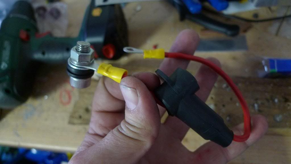
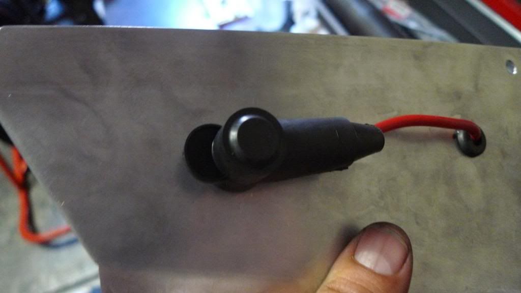
Note the cap. It is one of those sorts that cover the terminal on the starter motor. Sure it is okay to have a +ve terminal somewhere, and I not an expert, but I reckon it is probably pretty important to cover it up when not is use .. hence the cap.
The cap needs to be popped on and off the external terminal, so some of the wire needs to run outside the side plate to slide the cap along. So, I'll drill two holes - one for the bolt and another for the wire to come though.
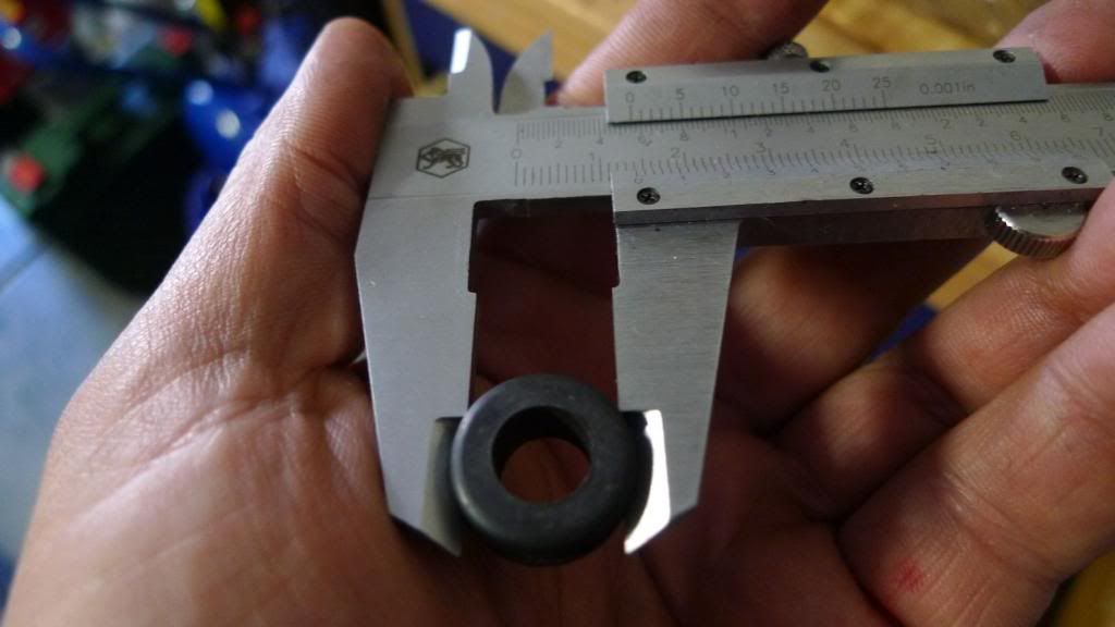
The grommit to fit the 8mm terminal bolt was pretty wide - 13mm in fact, geeez. That needs a big drill bit .. so I had to scrounge:
Drilled and mounted .. it looks a bit like this:
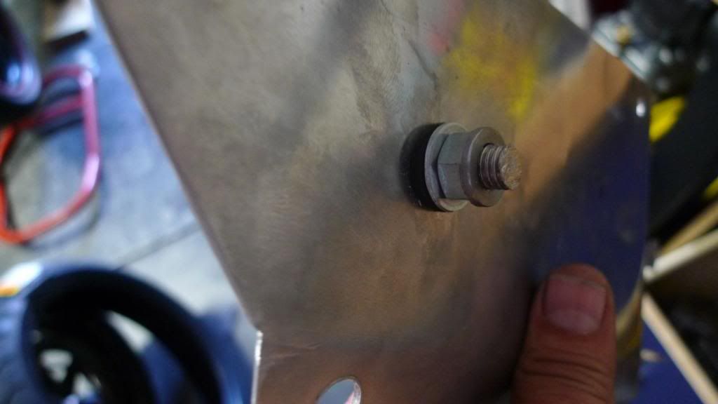
Note the upside-down flange nut - this was to give a lip that the cap would 'pop' over.
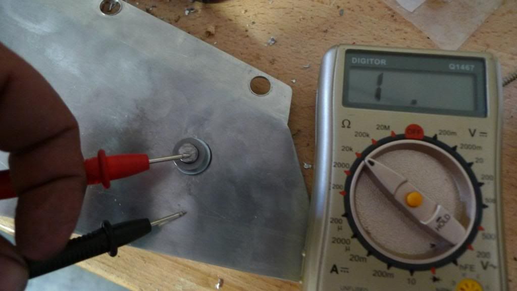
It is important that the terminal is insulated from the bike and this is what the grommit is for - but a quick test to show that the new terminal is insulated shows it is. Nice.
Now you see it:

Now you don't:
Mounted on the bike and connected up it looks like this:
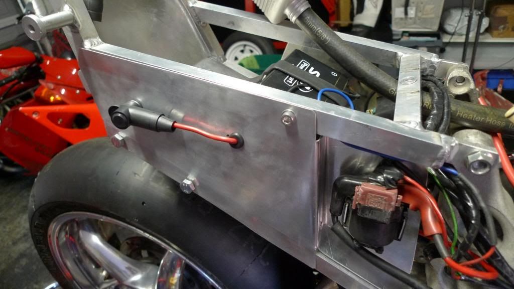
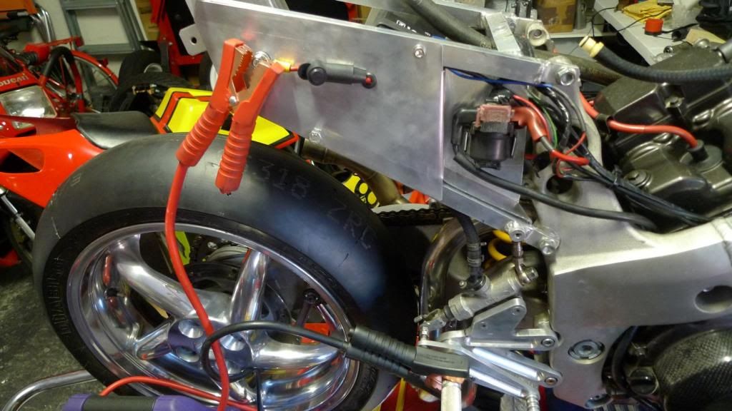
Putting theory into action this shows what I mean. Note the +ve from the jump box to the new external terminal and the -ve goes to the foot peg. The bike turns over fine and the wire from the terminal does not heat up:
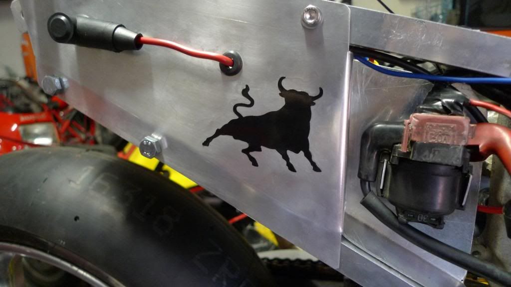
Cool. We're getting there with this damn battery box ordeal. But now, a small token to make sure the old gods look after me on the track :-) :
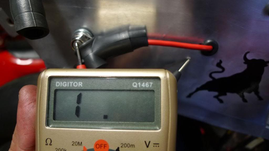
.. and now that everything is mounted it is worth a quick check again just to make sure the the terminal is insulated from the bike, and it is, so time to move on to other items in my list .... :
.. and a G&T ...

Ok, the bike runs total-loss so I need some way to a) jump start it, and b) charge the battery. Previously, I had the +ve and -ve run from the battery to an 'anderson' connector on the right subframe plate and made some matching connectors to start/charge etc.
But .. that was before .. this is now .. and the way I figure it, most of the bike is a -ve terminal, so I only need to have a external +ve somewhere to connect to. The -ve connection from the jump-box or charger can really be connected anywhere on the bike - like the footpeg or something. So, I'll give this a go .. that is, just mount a +ve point somewhere and that is all. I'll put an insulated bolt though the new subframe plate and wire it to +ve and that'll give me an external +ve terminal.
If this is crazy .. shout now!
So I made something like this:

Note the cap. It is one of those sorts that cover the terminal on the starter motor. Sure it is okay to have a +ve terminal somewhere, and I not an expert, but I reckon it is probably pretty important to cover it up when not is use .. hence the cap.
The cap needs to be popped on and off the external terminal, so some of the wire needs to run outside the side plate to slide the cap along. So, I'll drill two holes - one for the bolt and another for the wire to come though.
The grommit to fit the 8mm terminal bolt was pretty wide - 13mm in fact, geeez. That needs a big drill bit .. so I had to scrounge:

Drilled and mounted .. it looks a bit like this:

Note the upside-down flange nut - this was to give a lip that the cap would 'pop' over.
It is important that the terminal is insulated from the bike and this is what the grommit is for - but a quick test to show that the new terminal is insulated shows it is. Nice.

Now you see it:

Now you don't:

Mounted on the bike and connected up it looks like this:

Putting theory into action this shows what I mean. Note the +ve from the jump box to the new external terminal and the -ve goes to the foot peg. The bike turns over fine and the wire from the terminal does not heat up:

Cool. We're getting there with this damn battery box ordeal. But now, a small token to make sure the old gods look after me on the track :-) :

.. and now that everything is mounted it is worth a quick check again just to make sure the the terminal is insulated from the bike, and it is, so time to move on to other items in my list .... :

.. and a G&T ...