LED indicators - basic question
Forum rules
Please can you post items for sale or wanted in the correct For Sale section. Items / bikes for sale here will be removed without warning. Reasons for this are in the FAQ. Thanks
Please can you post items for sale or wanted in the correct For Sale section. Items / bikes for sale here will be removed without warning. Reasons for this are in the FAQ. Thanks
-
Cammo
- Site Supporter

- Posts: 4505
- Joined: Thu May 01, 2008 12:35 am
- Bike owned: NC30
- Location: Melbourne, Australia
LED indicators - basic question
Do I need some sort of resistor module to get LED indicators (front and back) flashing at the standard rate on an nc30?
Yet to buy some, want to get everything I need at once.
Tried a search but couldn't find what I was after.
Thanks.
Yet to buy some, want to get everything I need at once.
Tried a search but couldn't find what I was after.
Thanks.
"It's just a ride" Bill Hicks
-
eamer1989
- Settled in member
- Posts: 92
- Joined: Sat Sep 12, 2009 9:42 pm
Re: LED indicators - basic question
you will indeed cam, well depends they will flash slightly fast but not quiet a fail over here :)
-
mart
- Settled in member
- Posts: 81
- Joined: Thu Oct 01, 2009 10:20 pm
- Bike owned: sp1, sv650, nc30
- Location: ascot
Re: LED indicators - basic question
i think you can also buy a flasher relay to suit instead of 4 resistor blocks
-
stunc30
- Settled in member
- Posts: 12
- Joined: Tue Feb 02, 2010 2:42 pm
- Bike owned: nc 30 dt125mx
- Location: Rayleigh Essex uk
Re: LED indicators - basic question
ive seen replacement relays for led indicators as well but havnt tried them yet but if u use the large type resistor u should only need to use one as the whole indicator circuit works on resistance they do get quite warm though hence surrounded by heat sink i would mount it to frame. personally i would get replacement relay 
-
ozracer
- Settled in member
- Posts: 49
- Joined: Thu Oct 29, 2009 5:04 am
- Bike owned: NC30 Race Bike
- Location: Blue Mountains, Australia
Re: LED indicators - basic question
You need an electronic flasher relay. The flash rate is set by the electronics in the relay and doesn't rely on the heating and cooling of a bi-metalic strip like in normal relays. Easy to get from eBay or auto parts shops/auto electricians.
-
hardnutdvd
- Regular Member
- Posts: 608
- Joined: Fri Jan 01, 2010 8:50 pm
- Bike owned: RVF400 NC35
- Location: Bedford, Bedfordshire
Re: LED indicators - basic question
Halfords do them too...
-
Cammo
- Site Supporter
- Posts: 4505
- Joined: Thu May 01, 2008 12:35 am
- Bike owned: NC30
- Location: Melbourne, Australia
Re: LED indicators - basic question
Thanks for the replies, a new relay it is.
"It's just a ride" Bill Hicks
-
Cammo
- Site Supporter
- Posts: 4505
- Joined: Thu May 01, 2008 12:35 am
- Bike owned: NC30
- Location: Melbourne, Australia
Re: LED indicators - basic question
Update:
Took the easy option: LED flasher relay installed... fail! All 4 indicators flash at the same time. Must be something to do with the extra current going through the wiring with the led's installed.
I took the dash indicator light out even, thinking that this was the only part of the circuit that links the left and right indicator system, still no joy.
Have purchased some resistors to install, will install them in the next few days.
"It's just a ride" Bill Hicks
-
Cammo
- Site Supporter
- Posts: 4505
- Joined: Thu May 01, 2008 12:35 am
- Bike owned: NC30
- Location: Melbourne, Australia
Re: LED indicators - basic question
Nice quote.Cammo wrote:Update:
Took the easy option: LED flasher relay installed... fail! All 4 indicators flash at the same time. Must be something to do with the extra current going through the wiring with the led's installed.
Solution:
For peeps thinking of installing led indicators the easy fix is to fit an led flasher unit as suggested above, and remove the dash indicator lamp so that the left and right circuits are separated. There are ways around this and still being able to use the dash lamp, but some electronic components (diodes) are involved.
I just tossed the bulb... only Sunday riders tend leave the indicators in. Oops that could be me!
"It's just a ride" Bill Hicks
-
Cammo
- Site Supporter
- Posts: 4505
- Joined: Thu May 01, 2008 12:35 am
- Bike owned: NC30
- Location: Melbourne, Australia
Re: LED indicators - basic question
Update: Decided to get the indicator dash bulb working.
On the NC30 when you convert all indicators to LED's, whenever left or right indicators are selected all 4 will flash. The dash indicator bulb joins the left and right circuits together. This will happen regardless of which type of flasher relay you're using.
This isn't a problem when using the standard indicator bulbs because there isn't enough current to flash all 4 incandescent bulbs, but it is a problem with LED indicators because they require so little current to work.
3 solutions to this:
1. Remove the dash indicator bulb like I did above, but you won't know if you've left them on. Not a safe option.
2. Fit heavy duty resistors to all 4 indicators to soak up the extra current in the circuit. These can get very hot (because of all the current that they're resisting) and are a very dodgy solution IMO.
3. Fit diodes to the indicator dash bulb circuit to act as one way devices for the current. This is generally how oem setups get around the issue, so I chose to use this method.
You'll need to buy 2 IN4004 diodes (or IN4005/IN4007). They cost me a grand total of 5c each from an electronics store. Soldering and heatshrinking the joins is a good idea also.
Didoes:
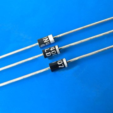
To fit them, find the wiring behind the dash for the indicator bulb - it's a light blue wire and an orange wire that goes to the bulb holder.
Cut them, leaving a good inch or so of wire on the bulb holder. Install the diodes (making sure they're around the correct way - silver band on the bulb side), and run both of these to just one of the bulb holder wires.
Run the other bulb holder wire to a suitable earth (there are several suitable locations on the back of the clocks - green wires).
Diagram:

Test it before you solder it and heatshrink it all together. All done!
On the NC30 when you convert all indicators to LED's, whenever left or right indicators are selected all 4 will flash. The dash indicator bulb joins the left and right circuits together. This will happen regardless of which type of flasher relay you're using.
This isn't a problem when using the standard indicator bulbs because there isn't enough current to flash all 4 incandescent bulbs, but it is a problem with LED indicators because they require so little current to work.
3 solutions to this:
1. Remove the dash indicator bulb like I did above, but you won't know if you've left them on. Not a safe option.
2. Fit heavy duty resistors to all 4 indicators to soak up the extra current in the circuit. These can get very hot (because of all the current that they're resisting) and are a very dodgy solution IMO.
3. Fit diodes to the indicator dash bulb circuit to act as one way devices for the current. This is generally how oem setups get around the issue, so I chose to use this method.
You'll need to buy 2 IN4004 diodes (or IN4005/IN4007). They cost me a grand total of 5c each from an electronics store. Soldering and heatshrinking the joins is a good idea also.
Didoes:
To fit them, find the wiring behind the dash for the indicator bulb - it's a light blue wire and an orange wire that goes to the bulb holder.
Cut them, leaving a good inch or so of wire on the bulb holder. Install the diodes (making sure they're around the correct way - silver band on the bulb side), and run both of these to just one of the bulb holder wires.
Run the other bulb holder wire to a suitable earth (there are several suitable locations on the back of the clocks - green wires).
Diagram:
Test it before you solder it and heatshrink it all together. All done!
"It's just a ride" Bill Hicks