Page 1 of 5
My Electrics Thread
Posted: Wed Nov 30, 2011 1:47 pm
by Man_Named_Dave
I'm double-checking my whole electrical system so I'm trying to go through the reg/rec tests on page 9.26 of the Haynes Manual. However the only check I get readings for are with the positive terminal attached to Green and negative attached to 3 Yellows (all under 200). Every other combination gives a reading of 1/Infinite, no matter which gradation I use. And yes, it's set to ohms

Also, can anyone help me with the Ignition Switch check on page 9.15? I really don't understand part 19.2.
Ta,
David
Re: My Electrics Thread
Posted: Wed Nov 30, 2011 2:13 pm
by Neosophist
Man_Named_Dave wrote:I'm double-checking my whole electrical system so I'm trying to go through the reg/rec tests on page 9.26 of the Haynes Manual. However the only check I get readings for are with the positive terminal attached to Green and negative attached to 3 Yellows (all under 200). Every other combination gives a reading of 1/Infinite, no matter which gradation I use. And yes, it's set to ohms
Also, can anyone help me with the Ignition Switch check on page 9.15? I really don't understand part 19.2.
Ta,
David
Copied and pasted from another thread at the moment.
Firstly set you multimeter to resistance, if it has a scale pick 200, the smallest one.
Step 1
Disconnect the plug with 3 yellow wires that connects to the reg/rec loom.
Call one wire A, one B and one C.
Put a probe on the following
A and B: __________
B and C: __________
A and C: ___________
Step 2
With the plug still disconnected set the multimeter to AC volts, 200 (lowest setting) should be fine.
Make sure battery is fully charged and start the engine (have the lights off)
A and B: __________
B and C: __________
A and C: ___________
Turn the engine off and reconnect the plug.
Step 3
Providing your regulator is wired up properly you can measure the voltage it is giving out at the battery.
Put the multimeter to DC volts, 20 will do.
Connect the -ve to the battery -ve and the +ve to the battery positive.
Measure the battery voltage with the engine turned off ______________________
Measure the battery voltage with the engine idling__________________________
Measure the battery voltage with the engine at 5000rpm _____________________
Measure the battery voltage with the engine idling and lights on _________________
Measure the battery voltage with the engine at 5000rpm and lights on ____________
What problems are you having?
Re: My Electrics Thread
Posted: Wed Nov 30, 2011 2:32 pm
by Man_Named_Dave
Arigato Neo,
I actually copied all these checks down from Xivlia's thread earlier today! Very handy.
The electrics were dodgy when I bought the bike and I've had a few issues in the past. A couple of months ago I had a starting issue. Since then I've discovered a continuity problem with the starter motor and bought a new battery (w/ higher cranking amps), and I would like to eliminate the reg/rec from my enquiries.
Currently though, I have to wait for a cam-cover bolt to arrive before I can re-fit the carbs and fuel tank, so those checks will have to wait a while. Thought in the meantime I'd do what I can to fix things.
Re: My Electrics Thread
Posted: Wed Nov 30, 2011 9:31 pm
by magg
Para. 19.2 in the Haynes manual refers one to the wiring diagram for the VFR which has a typo. The red wire from the battery should go to the BAT terminal on the ignition switch and the red/black wire from the IGN terminal on the ignition switch should go to the fuse box. The wiring diagram for the RVF, over the page, has it drawn correctly. Simply what should happen is when the ignition switch in the OFF position there should NO continuity between the red wire and the other wires from the ignition switch and in the ON position there should be continuity between the red/black wire and the other wires from the ignition switch.
Re: My Electrics Thread
Posted: Tue Jan 17, 2012 7:52 pm
by Man_Named_Dave
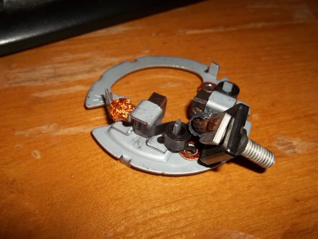
Ok, I decided to check the starter motor assembly.
The brush to the right is attached to the terminal bolt and has continuity to it. The brush on the left has no physical connection and no continuity. Do I need to solder some wire from the terminal bolt to the tab that's connected to the left-hand brush?
Cheers.
Re: My Electrics Thread
Posted: Tue Jan 17, 2012 9:05 pm
by magg
The brush on the left appears/should to be connected to the metal frame by a multi strand wire. This is the correct arrangement.
Re: My Electrics Thread
Posted: Wed Jan 18, 2012 9:20 am
by porndoguk
one goes to the earth/chassis (one of the left) the other the live goes to the M6 thread which then goes to the starter solenoid. looks ok, i wouldnt go soldering nothing as this is a VERY hot working high current piece of kit, you can get all these bits as spares i beleieve.
Rick
Re: My Electrics Thread
Posted: Wed Jan 18, 2012 6:19 pm
by Man_Named_Dave
Cheers guys,
Thanks for your input! :)
Re: My Electrics Thread
Posted: Sat Jan 21, 2012 4:31 pm
by Man_Named_Dave
I've been feeling a bit blond today so I have 2 silly questions:
1) How do I reconnect the starter motor? Does the ring connector sit between the 2 nut washers?
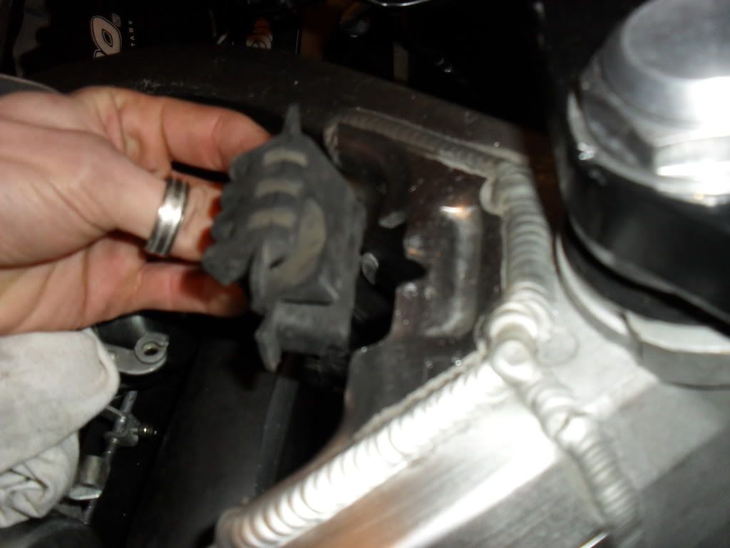
2) Can anyone tell/show me how the front grommet fits with the fuel tank? I can't fathom it at all.
Cheers,
David
Re: My Electrics Thread
Posted: Sat Jan 21, 2012 4:54 pm
by spud
i can help you with the tank gromet but not the other queston


hope its a help to you
cheers sam